
Available since version V1.52f
This output takes the speed signal measured at the S2a analog input and converts it to a pulsed signal with 500 clicks per meter on a configurable digital output. This output signal can then be used to distribute the exact same speed signal to an encoder input on one or multiple S2a units for exact and consistent position measurement.
Function:
This feature adds a new digital output function ‚VtoF converter‘ to the Shark 2a output configuration menu. It performs the following operations:
- — The analog speed signal is measured every 0.1 ms and from this the distance traveled is calculated
- — For every 2 mm a pulse with a high / low ratio of 1:3 is generated on a configurable digital output. Meaning the signal will be high for 0.5 mm and low for 1.5 mm and thus generating 500 clicks per meter.
- — The function is meant to be used as a way to convert an analog speed signal to a digital encoder signal to provide consistent position measurement across multiple Shark2a units
As an alternative use-case the VtoF converter’ can also be used with a fixed speed (AUTOSPEED = no, SPEED mm/s = correct conveyor speed). This outputs a stream of pulses relative to the entered speed – like described above – whenever the conveyor is running and no pulses while the conveyor is in stopped state.
To signal the current conveyor state to the S2a an input like ‘conveyor level’ together with an output of ‘conveyor start’ (which might be even be not connected) can be used.
If no conveyor input and output signals are configured the ‘VtoF converter’ output will just constantly output a stream of pulses – no matter if the conveyor is running or not.
Setup:
Make sure that the digital output ‘VtoF converter‘’ and digital input ‘encoder’ is not yet configured in the SYSTEM>IN/OUT MENU
Step 1 – Make sure that the digital output ‘VtoF converter‘’ and digital input ‘encoder’ is not yet configured in the SYSTEM>IN/OUT MENU
MultiSense – IN/OUT MENU in LF and HF shall not have any set to ‘VtoF converter‘, ‘encoder’, ‘heartbeat’.
Step 2 – Set parameter SYSTEM MENU>AUTOSPEED MENU>AUTOSPEED = yes
MultiSense – set HF and LF both to AUTOSPEED = yes

Step 3 – Perform the analog autospeed calibration according to the Shark2a operator manual or online documentation at https://docs.cassel-inspection.com/md/autospeed-menu
MultiSense – Do the autospeed calibration only at HF
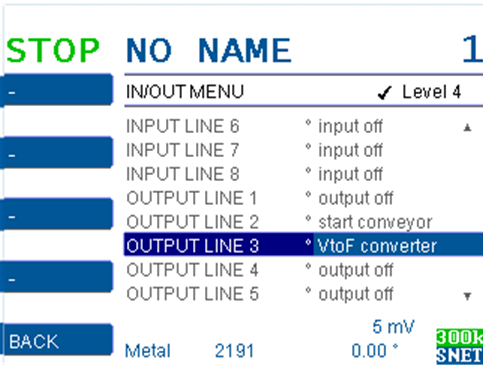
Step 4 – Configure one of the available digital outputs in the SYSTEM>IN/OUT MENU to ‘VtoF converter’
MultiSense – set HF OUT1 = VtoF converter
Step 5 – Set the parameter ENCODER clicks/m= 500
MultiSense – set HF and LF both to ENCODER clicks/m= 500

Step 6 – Configure one available digital input to ‘encoder’:
MultiSense – set HF IN8 = encoder
MultiSense – set LF IN8 = encoder

Final comments:
The signal at the output ‘VtoF converter’ will now generate an accurate conversion of the measured voltage at the analog speed input to a frequency, corresponding to the distance traveled per time.
The VtoF converter signal can now be looped back via cable to an encoder input on the same or different Shark mainboards and be operated in the same way as with a physical encoder:
Example:
The SHARK Multisense has two units (HF and LF) which rely on exact conveyor position measurement:
- Calibrate the analog speed on the HF mainboard as described above
- Set up the HF Mainboard with a ‘VtoF converter’ digital output
- Set up both units with an ‘encoder’ digital input
- Wire the VtoF converter output of the HF with a Y-cable to both encoder inputs of HF and LF mainboard
Both units will now measure their speed and distances based on the exact same input signal generated on the HF unit.
For a configuration without an Analog-Speedsignal at the Multisense, use this setup:
- HF: AUTOSPEED = off
- HF: SPEED mm/s = correct belt speed
- HF: INPUT Y = ‘conveyor level’ (von Kundensignal)
- LF: AUTOSPEED = on
- HF: OUTPUT X = ‘VtoF converter’
- HF : OUTPUT Z =’conveyor start’ (nicht connected)
- HF & LF: INPUT = ‘encoder’ + Y-Kabel von HF OUTPUT X