
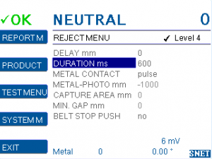
Settings for reject device timing and photo cell triggering.
DELAY mm
Delays the metal output signal for a certain distance. Usually it is set to the distance between photo sensor and pusher for proper reject timing.
Time of delay is based on DELAY mm and SPEED mm/s.
Note: During the delay period other metal signals which occur are stored in a shift register and are not lost.
Default: 0 [Millimetres]
Range: 0 – 30,000 [Millimetres]
DURATION ms
Sets the duration of a metal output pulse signal. E.g. use this to setup how long a reject signal remains active.
Note: While the relay is switched on, other metal signals which occur are stored in a shift register and are not lost.
Default: 500 [Milliseconds]
Range: 20 – 30,000 [Milliseconds]
METAL CONTACT
Programs the function of the metal alarm outputs.
Can be set differently with each product number, or same with all.
| pulse | Metal Alarm as a pulse with the duration DURATION ms. Use e.g. when pneumatic nozzles separate the metal |
| gf1 | Drives reject flaps with gravity feed applications. Error = flap in reject – position |
| gf2 | Drives reject flaps with gravity feed applications. Error = flap in ok – position |
| mesep | Metal separator model MESEP® SE |
| inline | Security drive of inline reject EX-PWC |
| hold | Standard value for belt stop with reset push button. Can also be set for GF type metal detectors. Reject will continue normal operation, but signal lamp will show metal alarm until manually reset. |
| push1 | Photo sensor has 0V with beam interrupted (input ‘reject sync’). |
| push2 | Photo sensor has 24V with beam interrupted (input ‘reject sync’). |
| push3 | Pusher without photo sensor synchronization. Input ‘reject sync’ not used. |
| pulse-2 | Metal Alarm as a pulse with the duration DURATION ms. Output met-2 signals the metal detection. Output metal is inactive. All other metal outputs brhave as normal. Enables to have two separate detection outputs depending on the product number. |
Default: pulse
NOTE – All below settings require that the MD is set as HowTo: Pusher setup
HowTo: Pusher setup
METAL-PHOTO mm
Sets the distance between metal detection and photo sensor.
STEP 1 – select PRODUCT 0
https://docs.cassel-inspection.com/md/select-and-edit
STEP 2 – set SENSE MIN mV
https://docs.cassel-inspection.com/md/teach-setup
STEP 3 – go to METAL-PHOTO
Set the cursor on the METAL-PHOTO and wait a few seconds, until the yellow notification bar comes up on top of the screen. Follow the instructions in the yellow notification bar to set an appropiate value.
With a photo eye mounted before the metal detector it will be a negative number marked “-“.
More detailed instructions can be found here, in the METAL-PHOTO section:
https://docs.cassel-inspection.com/md/howto-pusher-setup
Default: depends on application
Range: -4999 – 4999 [Millimetres]
CAPTURE AREA mm
A metal detector does not see the exact position of contaminations. A metal detector only detects the approximate position of a metal contamination.
To ensure the correct reject of the contaminated product pack these conditions have to be fullfilled:
- A photo sensor has to be installed before the metal detector to identify single product packs, their position and length (set up photo sensor in IN/OUT MENU: SYSTEM MENU > IN/OUT MENU > REJECT SYNC).
- The contamination has to be assigned to a certain product pack based on the data provided by the photo sensor.
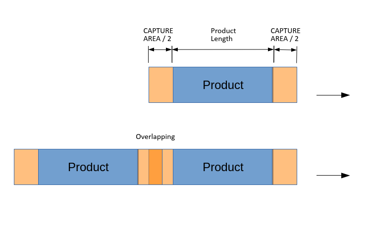
CAPTURE AREA mm is the tolerance that is added to product front and again at product tail. Total product scan area is CAPTURE AREA/2 + PRODUCT LENGTH + CAPTURE AREA/2. The PRODUCT LENGTH is determined by the photo sensor.
In case the capture areas of two product packs are overlapping, the reject will push both packs if a contamination is assigned to the overlap area. This ensures, that also contaminations located on the borders of a product pack are rejected reliably.
CAPTURE AREA mm = 0 is an automatic mode. It sets a suitable area depending on the sensor head size (field width).
The yellow notification bar suggests a suitable setting for capture area.
When should CAPTURE AREA mm be set to zero and when should there be a value input?
Step 1/ Start your setting with zero:
CAPTURE AREA mm = 0 is an automatic mode. It sets a suitable area depending on the sensor head size (field width).
Step 2/ Run product packs, with a gap as in the actual production. Add a test piece to one pack.
Is only one pack rejected? Then keep zero.
Are two or more packs rejected, eg because of a small pitch? Then play with CAPTURE AREA. You typically want to set it to small numbers, such as 10 to 50 mm.
Do the packs shift or slide on the belt? Then play with CAPTURE AREA. You typically want to set it to large numbers, such as 50 to 300 mm.
Default: 0
Range: 0 – 999 [Millimetres]
Note: For this setting you need a photo sensor.
Note: This function was modified with V1.14f
MIN.GAP mm
With this setting it is possible to check products which have gaps ( e.g. various parts in plastic). It is possible to distinguish between gaps in products and gaps between two products. Set the maximum length a gap in one product can have. Any gap bigger than this will be detected as gap between two products. If the product has gaps and is not configured this way, in case of a metal alarm the pusher eventually will not hit the product in the middle.
Note: For this setting you need a photo sensor.
BELT STOP PUSH
Range: no/yes/hold/cw
Default: depends on application
BELT STOP PUSH = no
With pusher: The conveyor belt does not stop while product is pushed.
BELT STOP PUSH = yes
With pusher: The conveyor belt stops for DURATION ms while product is pushed.
BELT STOP PUSH = hold
Without pusher, with stop-on-detect: The conveyor belt stops when contaminated product reaches the push position and waits for manual confirmation of metal alarm and manual restart of the conveyor belt. This allows a system without a physical pusher to behave like configured METAL CONTACT=hold, even though it is set to METAL CONTACT=push1 or push2 (as required for MultiPhase).
BELT STOP PUSH = CW reject
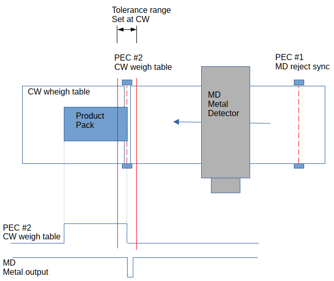
Metal output works as a reject signal for Teltek Checkweigher Combo, in this configuration: The metal detector is installed in the inlet of the CW. There is a photoelectric sensor in front of the MD (reject sync) and another photoelectric sensor (in front of the weighing table, connected to the CW).
With BELT STOP PUSH =CW reject does the MD metal output trigger to the product end. Adjust DELAY mm so that the metal output comes when the product end runs through the photoelectric sensor (in front of the weighing table). Available since firmware 1.52c10, Juni 2022.
Comments 1
Comments are closed.