Step by step instructions for a proper pusher operation.
A pusher reject shall hit a product pack in the pack center. Therefore the SHARK electronic must know when the product pack is positioned in front of the pusher. A metal detector needs a photo sensor to recognize the position of a product pack. The SHARK synchronizes a metal detection with the photo sensor signals, and thus enables the metal detector to activate the pusher once the product pack is in front of the pusher.
A metal detector does not see the exact position of metal contaminations. A metal detector only detects the approximate position of a metal contamination. To ensure the correct reject of the contaminated product pack these conditions have to be fullfilled:
- Photo sensor: A photo sensor, installed before the metal detector, to identify single product packs (pack position and length).
- Software settings: A metal detection must be assigned to one or more product packs. The proper synchronization of metal detection and product pack and the reject timing is controlled by software settings.
Overview
- Step 1/ Photo sensor position
- Step 2/ Pusher position
- Step 3/ Pusher wiring
- Step 4/ Set SPEED mm/s (=speed as product passes the sensor head)
- Step 5/ Set IN/OUT Menu: input (reject sync), output (pusher 1/1 or pusher 1/3)
- Step 6/ Set METAL CONTACT (photo sensor 24/0V=push1, 0/24V=push2)
- Step 7/ Set DELAY mm (distance photo sensor to pusher in mm)
- Step 8/ Set METAL-PHOTO mm
- Step 9/ Set CAPTURE AREA mm (default=0)
- Step 10/ Set MIN.GAP mm (default=20 mm)
- Step 11/ Set BELT STOP PUSH (optional) (no, yes, hold)
- Step 12/ Set DELAY mm (fine tune until pusher hits product center)
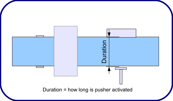
- Step 13/ Set DURATION ms (pusher activation duration)
Photo Sensor
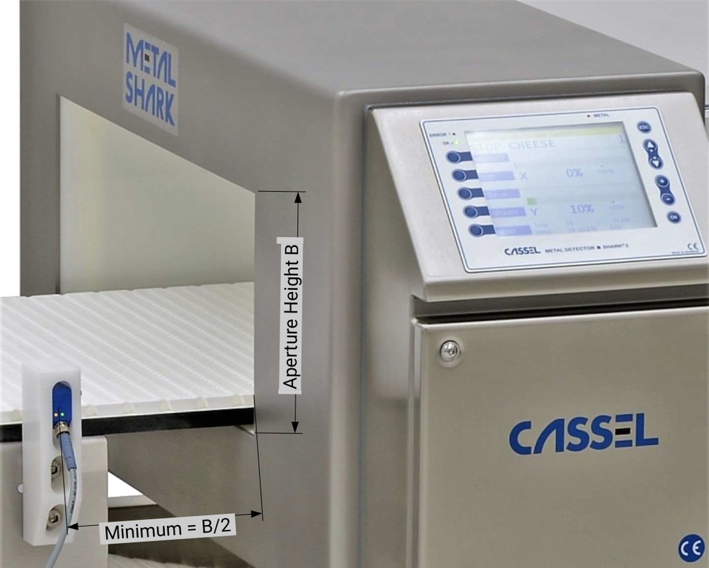
Step 1/ Photo sensor position
The photo sensor shall be installed before the sensor head. The minimum gap between a BD sensor head and photo sensor = Aperture height B/2 (due to the metal free zone).
Photo sensor type = 24V, PNP, with reflector on opposite conveyor side. PNP means that 24V are switched through to the photo sensor output.
Note: NPN type will NOT work. NPN would require to add a pull up resistor to the 24V input at the SHARK 2A mainboard.
Note about the monitoring of the photo sensor function (ERROR 23, warning):
https://docs.cassel-inspection.com/md/error-messages
Step 2/ Pusher position
The pusher shall be positioned after the sensor head.
Check these two distances:
A/ 2 x aperture height = ___________mm
B/ (1 x aperture height) + (0,5 x maximum product length) = ____________mm
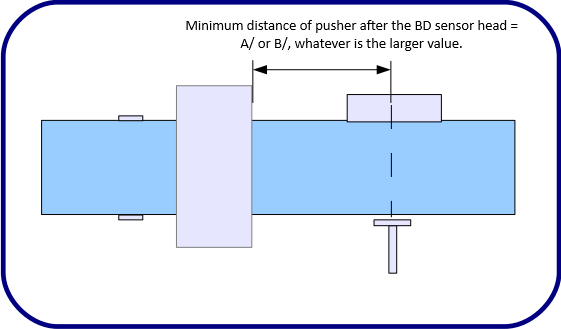
Minimum distance of pusher after the BD sensor head = A/ or B/, whatever is the larger value.
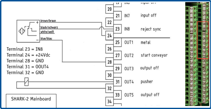
Step 3/ Pusher wiring
24V Photo sensor = any of the inputs IN1-8 INPUT 1-8
24V Pusher solenoid = any of the outputs OUT1-8 OUTPUT 1-8
Software settings
Step 4/ Set SPEED mm/s
Open SYSTEM MENU
IMPORTANT: The speed setting has to be correct, otherwise the software is not able to correctly calculate the reject timing!
SHARK-2/2A with CASSEL conveyor control box:
All settings are already set at CASSEL factory.
SHARK-2/2A without CASSEL conveyor control box:
1. Measure the belt speed with a speed meter in mm/sec
measured belt speed is __________________mm/sec
2. Set
– SYSTEM MENU > AUTOSPEED MENU > AUTOSPEED > no
– SYSTEM MENU > SPEED > measured belt speed
Note: To check if the SPEED mm/s setting is correct, refer to SPEED TEST mm at https://docs.cassel-inspection.com/md/autospeed-menu.
Step 5/ Set IN/OUT Menu
Open SYSTEM MENU > IN/OUT MENU
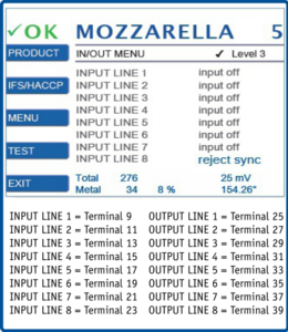
For the 24V photo sensor set INPUT LINE x = reject sync
For the 24V reject solenoid set OUTPUT LINE x = pusher 1/1 or pusher 1/3
Further info: https://docs.cassel-inspection.com/md/in-out-menu
IMPORTANT: The OUTPUT has to be pusher 1/1 or pusher 1/3. Output metal or metal inverse does not work with a pusher.
Step 6/ Set METAL CONTACT
Open PRODUCT MENU > REJECT MENU > METAL CONTACT
| push1 | Photo sensor has 0V with beam interrupted. |
| push2 | Photo sensor has 24V with beam interrupted. |
Note: Only use METAL CONTACT = push1 or push2 when any input is set to ‘reject sync’ and a photo sensor connected. Further info at https://docs.cassel-inspection.com/md/reject-menu
Note: Push1 includes a fail safe monitoring. Push2 is without fail safe monitoring.
With push1 the photo sensor function is monitored. A permanently blocked photo sensor throws the ERROR 23 Photo Sensor. The blocked distance that triggers the error is set with PHOTO EYE ERR mm.
Further information at
https://docs.cassel-inspection.com/md/brc-menu
https://docs.cassel-inspection.com/md/error-messages
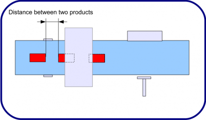
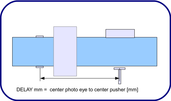
Step 7/ Set DELAY mm
Open PRODUCT MENU > REJECT MENU > DELAY
Set Delay mm to the distance between photo sensor and pusher:
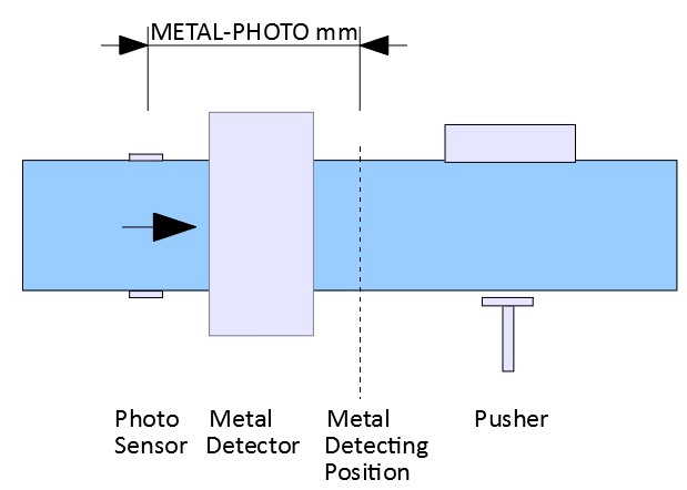
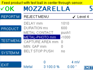
Step 8/ Set METAL-PHOTO mm
Open PRODUCT MENU > REJECT MENU > METAL PHOTO mm
The distance between photo sensor and the point, where the metal detector detects the metal, without adding the delay for the pusher. The metal detector typcially detects the metal once the metal object has just fully passed through the sensor head.
STEP 1 – select PRODUCT 0
https://docs.cassel-inspection.com/md/select-and-edit
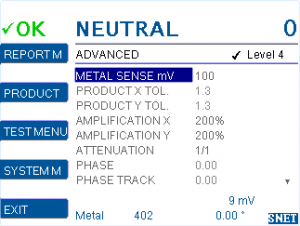
STEP 2 – set SENSE MIN mV
https://docs.cassel-inspection.com/md/teach-setup
STEP 3 – go to METAL-PHOTO mm
Set the cursor on the METAL-PHOTO line and wait a few seconds, until the yellow notification bar comes up on top of the screen. Follow the instructions in the yellow notification bar to set an appropiate value.
With a photo eye mounted before the metal detector it will be a negative number marked “-“.
Now carefully follow the instructions:
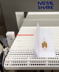
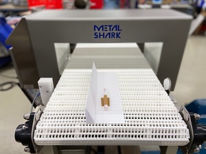
Feed product with test ball in center through sensor.
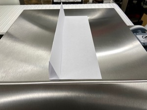
1/ Fold a simple sheet of paper – A4 or legal size – into an L-shape.
The folded part pointing upwards must be long enough to safely interrupt the photo sensor.
2/ Choose a test ball and set detection threshold.
| Example: Passing the Test ball is 500 mV | Set METAL SENSE to 80% of the test ball mV 500 x 80% = 450mV Read here how to set METAL SENSE mV |
 |
3/ Attach the test ball exactly in the center of the folded sheet of paper:
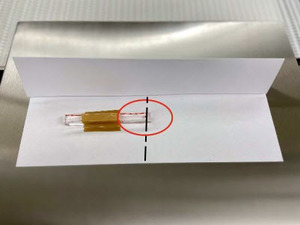
4/ Place the folded sheet of paper on the conveyor belt, before the photo sensor.
 correct position
5/ Start the conveyor. Let the folded sheet of paper pass through the metal detector.
6/ Read and take note of the suggested METAL-PHOTO mm from the yellow notification bar.
7/ Repeat steps 4/ to 6/ about 3 to 5 times.
8/ Choose an average value from the values indicated in the yellow notification bar and set it
for METAL-PHOTO mm.
A typical METAL-PHOTO mm value is in the range -300 to -1200 mm.
Note: METAL-PHOTO mm is only used when any input is set to ‘reject sync’.
Step 9/ Set CAPTURE AREA mm
Open PRODUCT MENU > REJECT MENU > CAPTURE AREA mm
Recommendation: Set as per the yellow notification bar.
Before version 1.50a: Minimum shall be the aperture height B [millimeter] of the BD sensor head.
From version 1.50a: Set 0 for auto setting of capture range.
Further info: https://docs.cassel-inspection.com/md/reject-menu
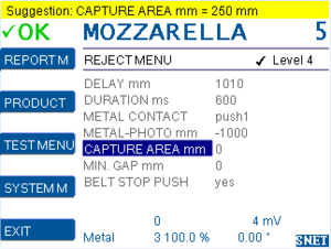
Note: CAPTURE AREA mm is only used when any input is set to ‘reject sync’.
Step 10/ Set MIN GAP mm
Open PRODUCT MENU > REJECT MENU > MIN.GAP mm
Before a new product pack can be triggered: The photo sensor beam needs to be uninterrupted for the length of MIN.GAP mm.
Set MIN.GAP mm = 0 (with none – transparent products)
Set MIN.GAP mm = length of a transparent product part (with fully or partly transparent product) plus some reserve.
If unsure, set MIN.GAP mm = 20.
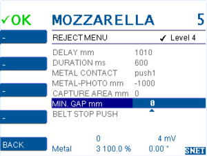
Note: MIN.GAP mm is only used when any input is set to ‘reject sync’.
Step 11/ Set BELT STOP PUSH (optional)
Open PRODUCT MENU > REJECT MENU > BELT STOP PUSH
| BELT STOP PUSH = no | With pusher: The conveyor belt does not stop while product is pushed. |
| BELT STOP PUSH = yes | With pusher: The conveyor belt stops for while product is pushed. The stop duration is DURATION ms. Note the in/out menu > output settings pusher 1/1 and pusher 1/3. Typically used if product packs lay very close with only little pitches or if the conveyor belt has a wide width. |
| BELT STOP PUSH = hold | Without pusher, with stop-on-detect: The conveyor belt stops when contaminated product reaches the push position and waits for manual reset of metal alarm and manual restart of the conveyor belt (by OK button or by input met/err reset). |
|
BELT STOP PUSH = CW reject
|
Metal output works as a reject signal for Teltek Checkweigher Combo, in this configuration: The metal detector is installed in the inlet of the CW. There is a photoelectric sensor in front of the MD (reject sync) and another photoelectric sensor (in front of the weighing table, connected to the CW). |
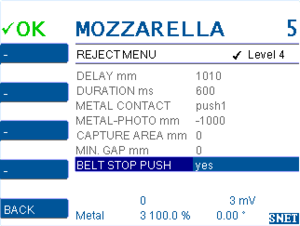
Note: Only use BELT STOP PUSH = ‘yes’ if any output is set to ‘conveyor on/off’.
Note: BELT STOP PUSH is only used when any input is set to ‘reject sync’.
Step 12/ Set DELAY mm again
Open PRODUCT MENU > REJECT MENU > DELAY
Pass products and fine tune Delay mm until the pusher hits the product center:
Step 13/ Set DURATION ms
Open PRODUCT MENU > REJECT MENU > DURATION ms
DURATION ms is the pusher activation time. Try various settings until the pusher properly rejects the product pack.
Double Rejects
Double rejects can have various reasons:
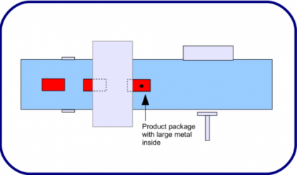
Large metal objects will cause a long term metal signal. During the duration of this metal signal more than one product pack can pass the metal detector. The software will not be able to differ which product pack is contaminated. For safety reasons the software will cause the reject of all product packs that pass the metal detector during the long metal signal.
The distance between the single product packs should be the product pack length. Otherwise the software may not be able to assign the metal alarm to the correct product pack and reject more than one product pack for safetly reasons.